Multimeter Components
- Jan 13, 2025
- 5 min read
Using a Multimeter: Chapter 2
In this module, we will introduce you to the components of a multimeter. This includes dials, displays, and buttons. Skip to quiz!
1. The Display
The multimeter is made up of several components like:
A display,
A dial, and
Buttons
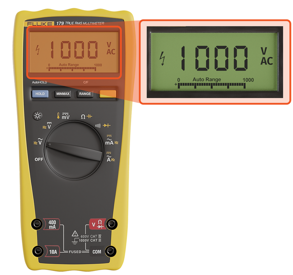
Let’s first go over what we see on the multimeter display.
The multimeter’s display shows us the value of our measurement, including the units. For example, you are measuring a 1000 volt wire. The meter will display 1000. The units will be “V” for volts. You will also see “AC” on the display since you are measuring AC voltage.
2. The Dial

The multimeter dial is a rotating circle in the center of your multimeter. Around the dial, you will see symbols for different multimeter measurements. To measure anything, you must rotate the dial so that it points at the symbol for what you want to measure.
For example, you are using the multimeter to the right. You want to adjust the dial to measure resistance. The symbol for resistance is “Ω”. Rotate the dial on the multimeter until the black mark on the dial points directly at the “Ω” symbol.
In order to use a multimeter, you need to understand what each symbol around the dial means. Without knowing the symbol, you cannot set the multimeter to measure what you want. Using the wrong symbol can damage the multimeter or result in electric shock.
3. Voltage Symbols

Recall that there are two types of current: direct current (DC) and alternating current (AC). With DC, the current only flows in one direction. With AC, the current will periodically alternate the direction it flows in.
The symbol for AC voltage will be a “V” with a wave over the top. The wave will look similar to the “~” symbol. The picture to the right shows a multimeter with the dial set to AC voltage. The wave above any symbol represents that the symbol is used on AC systems.
The symbol for DC voltage will be a “V” with a straight line and dashed line over the top. The picture to the right shows a multimeter with the dial set to DC voltage. The straight line and dashed line over any symbol represent that it is used on DC systems.

4. Current Symbols
The symbol for AC current will be a “A” with a wave over the top. The wave will look similar to the “~” symbol. The picture to the right shows a multimeter with the dial set to AC current.
The symbol for DC current will be a “A” with a straight line and dashed line over the top. The picture to the right shows a multimeter with the dial set to DC current.
5. Other Symbols

The continuity symbol looks like a wifi signal on its side. It looks like this “))))”. For continuity, it does not matter if the system is AC or DC. It will work for both. The picture to the right shows a multimeter with the dial set to continuity.
The resistance symbol looks like an “Ω”. For resistance, it does not matter if the system is AC or DC. It will work for both. The picture to the right shows a multimeter with the dial set to resistance.
The capacitance symbol looks like this “-|(-”. Capacitance is sometimes referred to as “farads”. Farads are the unit of measurement for capacitance. The picture to the right shows a multimeter with the dial set to capacitance.
The temperature symbol looks like a thermometer. The picture to the right shows a multimeter with the dial set to temperature.
6. Buttons
Your multimeter will also come with several buttons on it. In the next few slides, we are going to cover the most common buttons that you will see on a multimeter.
Normally, the value you are measuring will disappear when you remove your leads. When you press the hold button while taking a measurement, the value you measured will remain on the screen. The hold button can be useful when the measurement value is fluctuating too much to read it.

The min/max button stores the values your meter is reading. It will store the smallest value you measure, the largest value, and some meters will also store the average. When min/max is on, you will see “min/max” on your multimeter display.
The range button allows you to manually set the range on an auto ranging multimeter. Each time you click range, the unit of measurement will change on your display. For example, you can press range to have the multimeter show 1-3 decimal places on your measurement.
The function button allows you to access secondary measurements on your multimeter. If you look to the picture on your right, you will see symbols that are a different color. The symbols with different colors are accessed by turning your dial to the symbol and pressing the function key.
For example, in the multimeter to the right you can see a “-|(-”symbol above the “Ω”. That is the symbol for capacitance. To measure capacitance, you would rotate your dial until the dial points to “Ω”. You would press the function key and the “-|(-” symbol would appear on the display.
8. Conclusion
In this section, you learned about the components that make up a multimeter. You are now ready to take your first measurement!
Question #1: What does the display on a multimeter show?
The value of what you are measuring
The units of what you are measuring
What you are measuring
All of the above
Scroll down for the answer...

Answer: All of the above
The multimeter display will show the measurement you are taking, the value of the measurement, and the units.
Question #2: The multimeter dial is used to:
Change what is plugged into the port
Open the clamp on a clamp meter
Select what measurement you want to take
Scroll down for the answer...
Answer: Select what measurement you want to take
The multimeter dial is used to select the measurement you want to take.
Question #3: DC measurements have the following marking over the symbol:
A solid and dashed line
A wave
DC in capital letters
A circle around the symbol
Scroll down for the answer...
Answer: A solid and dashed line
DC measurements are always represented by a solid and a dashed line over the symbol.
Question #4: AC measurements have a wave over the symbol.
True
False
Scroll down for the answer...
Answer: True
True, a wave over any symbol indicates that the measurement is for an AC system.
Question #5: When measuring continuity, you must set the meter to AC or DC continuity.
True
False
Scroll down for the answer...
Answer: False
False, continuity is not dependant on the type of current. It works with both systems. There is only one continuity symbol.
Question #6: Capacitance is sometimes referred to as:
Kelvins
Farads
Mph
Tonnes
Scroll down for the answer...
Answer: Farads
Capacitance is sometimes referred to as Farads. Farads are the unit of measurement for capacitance.
Question #7: What does the range button do?
Tells you the accuracy of your multimeter
Lets you manually select the units of your measurement
Creates a beep sound when measuring above the range
Tells you the health of your fuse
Scroll down for the answer...
Answer: Lets you manually select the units of your measurement
The range button allows you to manually change the units of your measurement.
Question #8: To keep a value on your display after you stop measuring, you should select which button:
Hold
Range
Function
Min/Max
Scroll down for the answer...
Answer: Hold
Pressing the hold button while you are measuring will keep the value on the display.


