Refrigerant Recovery for Small HVAC Equipment
- Sep 17, 2025
- 11 min read
EPA Type 1 Chapter 2
Refrigerant Properties
In this module, we will take a look at how to read Pressure-Temperature charts. We will also discuss the pressure-temperature relationship of refrigerants and talk about how to use them to see whether there is non-condensable present.
Reading PT Charts
Each substance has a unique saturation pressure-temperature relationship. By this, we mean that for a known refrigerant, we know its saturation pressure given a temperature and vice versa.

If we list out all the saturation pressures of R-22 or HCFC-22 at different temperatures, we get a PT chart that looks like this. A PT chart is a saturation pressure-temperature chart.
To read this chart, let’s zoom in. The units for temperature are either °F or °C, as we can see up here.
The units for saturation pressure is given under where it says Pressure. In this case, the pressure will be given in units of psig.
To find the pressure at a temperature, we look for the temperature, then look across that row for the corresponding pressure. For example, at 10°F, we see that the saturation pressure at the temperature is 32.8 psig.
And at 50°F, its saturation pressure would be 84.1 psig. This means that the refrigerant R-22 will vaporize at a pressure of 84.1 psig if the temperature is 50°F. And vice versa, if the temperature is known to be 50°F, we know the pressure that the refrigerant vaporizes at is 84.1 psig.
Remember that this chart is specific to the refrigerant R-22. If we wanted to do this for another refrigerant, we would have to look up the PT chart for that refrigerant. For example, for the refrigerant R-134a, we would look up “R-134a PT Chart”
For the EPA exam, we need to know how to reference PT charts to:
Find a saturation pressure given a temperature, or
Find a temperature given a saturation pressure
For refrigerant blends, we will see two pressures in their PT charts:
Vapor Pressure, and
Liquid Pressure
This is because the different components of the blend may be in different states at a given temperature. This is the PT chart for R-404a, which is a near-azeotropic blend.
Recall that near-azeotropic refrigerant blends act almost like azeotropic blends. So the components in the blend have a small difference between their boiling points. We see this reflected in the small difference between liquid and vapor pressure in R-404a’s PT Chart.
Recall that zeotropic refrigerant blends contain components that have different boiling points. For refrigerant blends that are zeotropic, we will see a larger difference between the two pressures. For example, we see a much larger difference in the pressures with R-407c, which is zeotropic.
And recall that azeotropic blends contain components that have the same boiling point. For azeotropic, or near azeotropic blends, the difference between the liquid pressure and vapor pressure is much smaller, if there is one at all. For example, we see a much small difference in pressures in the near-azeotropic refrigerant R-404a.
Non-Condensables
The pressure-temperature relationship is kind of like the fingerprint of a refrigerant. We can look at a refrigerant’s PT chart to see what the pressure of a refrigerant has to be at a specific temperature.
We can use this pressure-temperature relationship to see if there are non-condensables mixed in with refrigerant. To use this relationship, we need to measure both the pressure and temperature of the refrigerant.
If we measure the temperature and pressure values of a refrigerant and they are not the same as in its PT chart, then there are non condensables present in the cylinder. Non-condensables in the refrigerant cause the refrigerant pressure to b

e different than what it’s supposed to be.
For example, let’s say we know that the refrigerant is R-22 and the temperature is 70°F. Then, the pressure of the refrigerant should be 121.4 psig.
If we measure the pressure to be 130 psig, then that means there are non-condensables present because the pressure does not match. If the pressure is 122 or 120 psig, this is close enough and the difference may be due to human error.
In order to use pressure and temperature readings to check for non-condensables, we have to know that the pressure and temperature are both stable in their readings. For example, if the temperature of the room is changing, from 70°F to 75°F, we cannot use those temperature values to compare against the refrigerant’s PT chart.
Let’s say we recover R-22 from a system into a recovery cylinder. And then we want to check if there are any non-condensables in the recovery cylinder.
We need to first make sure the pressure and temperature are stable. We need to first let the recovery cylinder rest and come to room temperature. This lets us know that the temperature won’t change in between readings because it is in equilibrium with the room temperature.
After the recovery cylinder comes to a temperature that is the same as your room temperature, you can then perform the following steps to verify its pressure:
Look at the system’s high side pressure, and
Use your PT chart to check what the pressure should be.
If the pressures are close, you do not have non-condensables in your refrigerant. If it’s not close, there are non-condensables present and you need to recover, evacuate, and recharge the system. We evacuate to get rid of the non-condensables.
In this module, we learned how to make sense of and use PT charts. We also learned how to use these charts to see if there are non-condensables in a cylinder of recovered refrigerant.
Recovery Requirements
In this module, we will take a look at the two main methods of recovering refrigerants and discuss the different requirements for each method.
System Dependent Recovery
System Dependent Recovery requires the pressure of a functioning compressor to recover refrigerant. This is also called passive recovery.
Recall that in any system, the matter will flow from high pressure to low pressure. Since the refrigeration system is pressurized and the compressor increases its pressure, we can use that pressure as our “high” point.
If we connect a non-pressurized refrigerant container to the system, the pressure of the container is lower than the pressure inside the system. The refrigerant will naturally flow from high to low, helping us recover our refrigerant. This is how system-dependent recovery works.
Passive recovery is limited to appliances with 15 lbs or less of refrigerant. This includes small appliances with 5lbs or less of refrigerant, like household refrigerators. These are appliances that we cover in Type I.
Self-Contained Recovery
Self Contained Recovery is the use of a recovery device that operates independently of the system you are recovering from. They have their own compressor, pump, or another mechanism to recover refrigerant. This is also called active recovery.
When recovering from small appliances, first identify the refrigerant that you are about to recover. Older refrigerators, particularly those built before 1950, may contain non-fluorocarbon refrigerants, which cannot be recovered with current recovery equipment.
Active recovery does the job much quicker than passive recovery. Recall that as the time to recovery increases, the chances of venting increase. So we want to minimize time spent recovering refrigerants.
Active recovery is required for systems containing more than 15 lbs of refrigerant.
Recovery Levels
There are different required levels depending on whether the appliance’s compressor is working.
When the compressor in Type I appliances is not working, the EPA Section 608 rules require recovering 80 percent of the charge amount on the appliance nameplate.

For appliances with working compressors, the EPA Section 608 rules require either:
Recovery of 90 percent of the nameplate charge, or
Recovery of the appliance to 4 inches mercury (in Hg)
For example, with a charge of 5 lbs on the appliance nameplate and a non-functional compressor, you would need to recover 80% of the charge or 4 lbs of refrigerant. For the same appliance with 5 lbs of refrigerant, we would need to recover 4.5 lbs of refrigerant if the compressor is working.
Operating Compressor
With an operating compressor, there should be a big enough pressure difference between the system and your recovery container. The pressure difference makes the refrigerant naturally flow from high to low pressure, into the recovery container.
Because there is sufficient pressure, you only need to have one access valve to recover the refrigerant. For a system with an operating compressor and a completely restricted capillary tube, we would attach one access valve on the high side of the system.
Non-Operating Compressor
If the compressor does not work in the appliance, there may be refrigerant trapped in the compressor oil. Technicians need to take measures to help release trapped refrigerants. This is especially important in passive recovery since the recovery process relies on the system pressure.
It is essential to take measures to help release trapped refrigerant when performing passive recovery and the compressor is not working. Since refrigerant is miscible in refrigerant oil, it can get trapped in the oil, but when we heat it up, the refrigerant vaporizes, separating it from the oil. This is how we can release the trapped refrigerants.
These measures for releasing trapped refrigerant include:
Warming the system (with a heating blanket or a heat gun), and
Tapping the compressor bottom with a rubber mallet to release refrigerant
Make sure we are only warming up the system with a heating blanket and not an open flame. Recall from Core that this can cause an explosion since refrigerant cylinders are pressurized and refrigerants may be highly flammable.
If we tap the compressor to release trapped refrigerant, make sure we are using a rubber mallet. We need to make sure that we are not damaging the appliance. If we use a metal mallet, this may damage the appliance and release refrigerant, damage equipment, or worse.
When performing passive recovery and the compressor is not working, we need to access the system from both the high and low sides to recover as much refrigerant as possible.
Because we are performing passive recovery, the recovery process depends on the compressor. With a non-operating compressor, we need to access both high and low sides to try to get to the 80% required level of recovery.
Technicians need to take measures like this to make sure that we can recover the required level of 80% of the nameplate charge when the compressor doesn’t work.
In this module, we discussed the requirements for recovering refrigerants in Type I appliances. For appliances with non-functional compressors, we need to recover 80% of the nameplate charge. This is required for both passive and active recovery.
And for active recovery on appliances with working compressors, we need to recover either 90% of the nameplate charge or to a 4-inch vacuum.
Recovery Procedure
In this module, we will take a look at how to recover refrigerants and ways to speed up our recovery process.
Recovery Overview
Before recovering any refrigerant, we need to first identify the refrigerant in the appliance. Then, we need to use a recovery cylinder that is used for that type of refrigerant. For example, if we are recovering from an appliance that contains R-22, we need to use a recovery cylinder that is exclusively used for R-22.
Recall that each recovery cylinder can only be used to recover one type of refrigerant. We need to keep recovery cylinders separate for different refrigerants to avoid mixing refrigerants and making the refrigerants unusable.
When recovering refrigerant into a recovery cylinder, we also need to make sure we do not fill more than 80% of the cylinder’s capacity.
We can monitor the fill of the recovery container by using one of the following:
Mechanical float devices,
Electronic shut off devices, or
Gross cylinder weight
Mechanical float devices are sometimes also called internal float devices. They work by turning the motor off on the recovery machine when a certain fill level has been reached.
But even if the motor is off, refrigerant can still flow into the cylinder, leading to a fill of more than 80%. If you then warm up the cylinder, it can then even explode or blow out a relief valve.
For these reasons, the industry has largely shifted away from mechanical or internal float devices and even electronic shut-off devices. But technically, these methods can still be used according to the EPA.
Using the cylinder weight is the most accurate method of monitoring fill level. This method forces technicians to be more vigilant and get recovery done in a more timely fashion, which reduces the risk of accidental venting.
Recovery Speed
Recall that we want to minimize our recovery time because the longer we take in recovering refrigerant, the more likely it is that an accident can happen. We want to prevent accidents like releasing refrigerants or equipment malfunction.
There are special cases where we have to take additional measures to recover refrigerant faster. This includes if we are doing passive recovery and the compressor stops working.
One of the methods we can use to recover refrigerant faster is to install both low and high side access valves. This way, refrigerant can flow through both sides, allowing us to recover refrigerant faster.
In frost-free refrigerators, we can also utilize the defrost heater component to help us speed up the recovery of refrigerants. The defrost heater is a component in frost-free refrigerators that melts ice off evaporator coils so that the coils can be exposed to air.
Turning on the defrost heater will increase the temperature of the refrigerant so that we can recover it faster.
In this module, we took a look at recovery practices including:
Identifying the refrigerant inside an appliance,
Methods to prevent overfilling recovery cylinders, and
How to increase recovery speed so we minimize recovery time.
Next, we’ll take a look at the equipment we need for refrigerant recovery.
Recovery Equipment
In this module, we will take a look at pieces of equipment that are commonly used when recovering Type I small appliances. We will discuss the EPA’s Section 608 regulations for these pieces of equipment.
Assess Fittings
There are many systems that are “sealed”, meaning they are essentially closed systems where the refrigerant inside is not accessible. These appliances do not come with ports installed for testing, recovery, charging, or evacuation.

Recall that hermetic systems are sealed systems, so this is a characteristic of Type I small appliances. Examples of these closed or sealed systems include window AC units and refrigerators.
In order to access these systems for service, we need to first look for process tubes. If there are no process tubes for us to access the refrigerant through, we can create an opening by installing an access fitting. We install access fittings into the sealed system to gain access to the refrigerant.
Make sure you have a good reason for opening up any sealed system! Access fittings must be leak tested before using them to recover refrigerant to make sure we are not venting refrigerant.
Piercing Valve
Piercing valves are used to access refrigerant from the process stub on small appliances. We can use both solder and solderless piercing valves.
Let’s say we have installed and opened a piercing access valve. If we find that the pressure of the appliance is 0 psig, this means there has been a leak. And the fact that the pressure is 0 psig indicates that there is basically no more refrigerant left in the system.
If the appliance is expected to leak often, we will generally use solder type piercing valves. This is because they are more durable and tend to hold up better over time.
Solderless piercing valves tend to leak over time, so they should not remain on the system after completion of service.
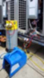
Low Loss Fittings
There are two main kinds of low loss fittings - automatic and manual. In this video, the fitting attached to the red hose is automatic, and the fitting attached to the yellow hose is manual. They both work by obstructing and preventing the flow of refrigerant from leaving the hose, which prevents the venting of refrigerants.
Low loss fittings are required for servicing systems containing CFCs, HCFCs, and HFCs to prevent from venting them. This is to comply with the Venting Prohibition, which applies to all ODS and their non-exempt substitutes.
For these systems, low loss fittings are required whenever refrigerant hoses are used in your service including when
Recovering refrigerant, and
Measuring system pressure
When we connect our hoses to measure the system pressure or to recover refrigerant there is a risk of releasing the refrigerant. That’s why low loss fittings are necessary.
Low loss fittings work just like your standard garden hose. If you just use a garden hose without a nozzle, you’ll see that even when you turn off the water, water still comes out of the hose.
If you have a nozzle on the other end of the hose, you can better control when the water stops flowing. This is basically the low loss fitting job.
In this module, we discussed the use of access fittings, piercing valves, and low loss fittings in our recovery procedures.
The EPA requires the following:
Access fittings must be leak tested before use
Solderless piercing valves cannot stay on equipment after servicing, and
Low loss fittings must be used whenever connecting refrigerant hoses with CFCs, HCFCs, and their substitutes.
Other References: